Working with cross sections
Cross sections are the most flexible way of viewing data and validating models at various angles, shapes, and locations. You can display a cross section in a 3D View
You can create cross sections in different ways:
- Via the Cross Sections drop-down list
 in the 3D View toolbar, where you find functionality to define an arbitrary cross section (see Creating cross sections with the 3D View toolbar) or access the Cross Sections form, which allows you to create cross sections based on coordinates or objects (see Creating cross sections using the Cross Sections form).
 - By using the context menus of surface representations or wells in the JewelExplorer or 3D View:
- Tri-meshes: Create > Create Surface-parallel Section
- Polyline Sets and Point Sets: Create > Create Vertical Section or Create > Create Planar Section
- Wells and well trajectories: Create > Create Vertical Section and Create > Create Wellbore Section.
- By using the Editing Tools when the CoView is the active view (see Graphically creating and editing cross sections).
All cross sections are stored in the Cross Sections folder in the JewelExplorer, taking the name of the (type of) cross section that you created ('Vertical Section', 'Plane Section'), or the name of the surface or well it is based on (e.g. 'Well A Section', 'Fault 1 Section'). When the cross section takes the name of the surface or well, you can recognize which type of cross section it is by the symbol in front of the name in the JewelExplorer.
There are three types of cross sections in JewelSuite Subsurface Modeling. Each type has its own features regarding the number and shape of the panes, and its rotation and moving options. Note that with 'rotation' is meant the fee rotation in all directions, while 'moving' refers to lateral movement along an axis.
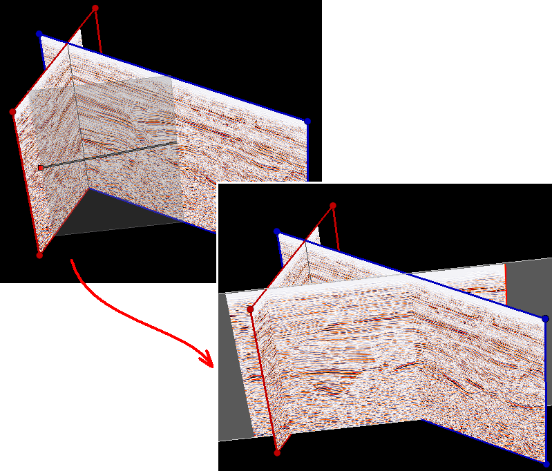
Vertical Section
![]()
- Contains one or more flat panes (Arbitrary Cross Section falls within this category). The only exception is the Wellbore Section, which can have curved (vertical) panes since it follows the wellbore in a curtain-like shape.
- Panes have 90 degrees inclination (i.e. they are vertical)
- Cannot be rotated
- Cannot be moved (only graphically altered) in a 3D View
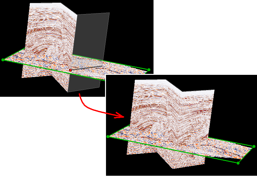
Planar Section
![]()
- Contains one flat pane
- Pane can have any inclination
- Can be rotated
- Can be moved
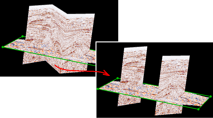
Surface-parallel Section
![]()
- Contains one or more non-flat panes (panes follow geometry of the reference tri-mesh)
- Cannot be rotated
- Can be moved
For more on rotating, moving and graphically adjusting cross sections, see Moving and rotating cross sections with the 3D cursor.
Creating cross sections with the 3D View toolbar
The Cross Sections drop-down list down list () in the 3D View toolbar allows you to create various types of cross sections:
![]() From the drop-down list, select Create Planar Cross-section, then click two locations to construct a vertical plane.
From the drop-down list, select Create Planar Cross-section, then click two locations to construct a vertical plane.
Constructing a plane cross section click to enlarge
![]() From the drop-down list, select Create Arbitrary Cross-Section, then click several locations to construct a vertical section based on the corresponding line.
From the drop-down list, select Create Arbitrary Cross-Section, then click several locations to construct a vertical section based on the corresponding line.
Constructing a vertical cross section click to enlarge
![]() From the drop-down list, select Delete a Pane of Cross-Section, then click the pane to be deleted.
From the drop-down list, select Delete a Pane of Cross-Section, then click the pane to be deleted.
Deleting a cross section pane click to enlarge
![]() From the drop-down list, select Delete an Edge of a Cross Section. This action will delete (collape) a pane between two cross section panes. Click on the edge you want to delete.
From the drop-down list, select Delete an Edge of a Cross Section. This action will delete (collape) a pane between two cross section panes. Click on the edge you want to delete.
Collapsing an edge click to enlarge
![]() From the drop-down list, select Open Cross-Section Form. See below how to use this form.
From the drop-down list, select Open Cross-Section Form. See below how to use this form.
Creating cross sections using the Cross Sections form
Use the Cross Sections form. It is opened via the drop-down list in the toolbar at the top of a 3D View.
-
Select the type of cross section that you want to create:
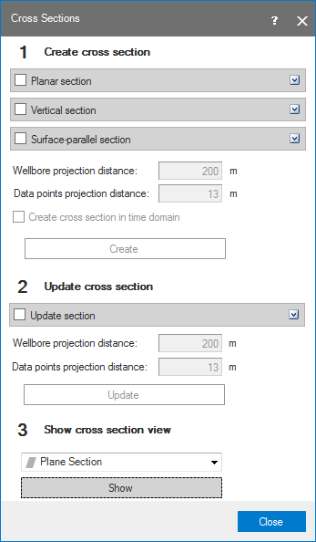

The Cross Sections form click to enlarge
Planar section A planar section is a flat display canvas extending through the 3D space as defined by the horizontal and vertical extremes of all objects in the solution. It consists of only one pane. Planar sections can be rotated in all directions.
Two points determine a line through which the plane section will go. Initially the generated pane is vertical.
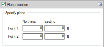
Specifying a planar section click to enlarge
Vertical section This option creates a vertical section based on existing data such as surfaces or well data. Vertical sections can consist of one or more panes.
Click the Polyline Set tab, then select the required polyline set to generate a section based on the polyline set.
Click the Wells tab to generate a section through wells. Select the wells from the list.
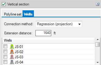

Vertical section through a well click to enlarge
Connection method Select one of the following:
Regression (projection) connects wells in the order of their projection on a regression line. The regression line is calculated using the lateral coordinates of the wells.
Genetic (shortest way) is a method that attempts to connect wells in such a way that the length of the section trajectory is minimal.
One VCS for each wellbore is a method that creates separate sections for each well. This method is most appropriate for wells in a ‘spider’ geometry, e.g. deviated wells drilled from a shared surface location, such as an offshore platform.
Extension distance is the parameter controlling the extension of well sections beyond the start and end locations of the wellbore trajectory.
For a single well you can also create a cross section with the option Create > Create Wellbore Section in the well’s right-click context menu.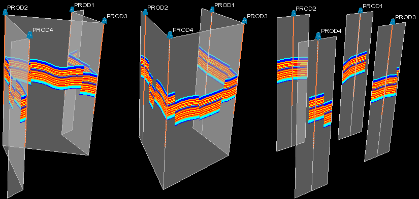

Examples of the different construction methods click to enlarge
Surface-parallel section This uses the existing tri-meshes to create the canvasses.
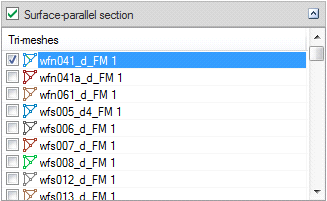

Select tri-mesh for the surface parallel section click to enlarge
Surface-parallel cross sections can be moved as phantom surfaces along predefined directions, vertical for horizon slices, horizontal along dip for fault slices.
Select the required tri-mesh in order to generate a surface section.
Wellbore projection distance This parameter defines the half-width of a 'corridor' around planar and vertical cross sections. Wellbores will be shown projected on the cross section view if they are partially or completely located inside the corridor.
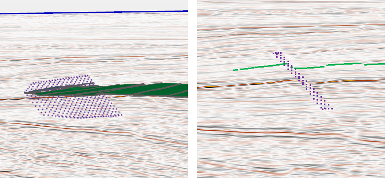
When you display wellbores or point set data on a cross section that consists of more than one pane in a Seismic View or a Cross Section View, JewelSuite projects the wellbores and point set data using a non-orthogonal method. An advantage of the non-orthogonal projection is that you will get a consistent cross-section in either view, i.e. objects are projected in the right order, which is less likely to be the case for orthogonal projection.
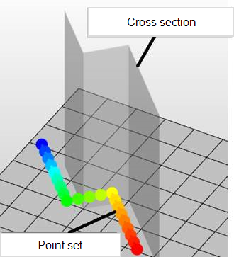

Point set with distance to cross section. When viewing this point set projected on the cross section in the Seismic View or Cross Section View, a non-orthogonal method is used. click to enlarge
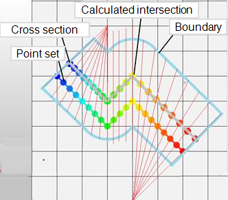

Projection using a non-orthogonal method. This method is chosen to prevent duplication and blind spots around the corners of the cross section panes when displaying wellbore or point set data. click to enlarge
The greater the projection distance, the larger the (possible) distortion of the projected wellbores and point set data, and the higher chance of a mismatch between cross-section backdrop data (e.g. seismic, 3D grid properties) and the projected wellbores and point set data. This effect does not occur when you display wellbores and point set data on a single pane cross section, i.e. a plane section.
Tips for visualizing wellbores and point set data on cross sections
- For single wellbore display, use a wellbore section which follows the wellbore like a curtain. This mitigates the risk of distortion due to projection. To create a wellbore section, you can use the wellbore's context menu Create > Create Wellbore Section or use the Wellbore Section form on the plan strip, see Creating a wellbore section.
-
For multi wellbore or point set cloud display, keep the cross-section pane as close as possible to the wellbore trajectory or point set cloud, and apply a shorter projection distance. You can create the cross section pane graphically using the cross section tool ( ) in the 3D View. For wellbores you can also create such a connected wellbore section using the cross-section form
- Use a combination of the 3D View and Cross Section/Seicmic View to be aware of possible projection artifacts.
Data points projection distance defines the half-width of a ‘corridor’ around planar and vertical cross sections. Nodes of point sets that are located inside the corridor, will be projected on the cross section view (see image below).
Create cross section in time domain Check this if you want to generate a section in time domain.
Create Generate the specified section.
Point set of fault projected on cross section (right) click to enlarge
-
Cross sections Select the section that must be updated.
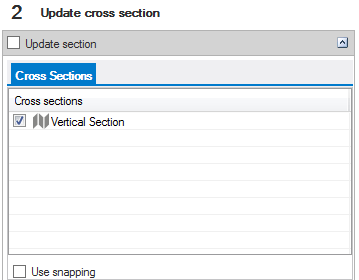

Select the section you want to update click to enlarge
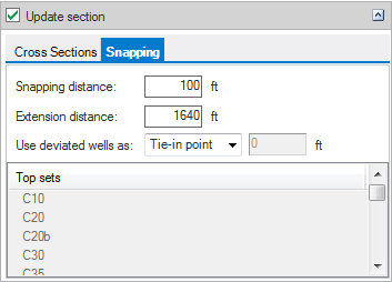
Snapping is only available for vertical sections.You can update a cross section by specifying a new Projection distance.

click to enlarge
When you select a vertical cross section, you can also select Use snapping.
Snapping updates the cross section and snaps it to selected positions on the well trajectories of the original well and additional wells.
Snapping distance defines the half-width of a corridor around an existing cross section. For wells to be included in the snapping process, they must be located in the corridor.
Extension distance is the distance by which well-specific panels will be extended.
Use deviated wells as Choose from various methods of defining how deviated wells are included in the resulting cross section:
Tie-in point Cross section is snapped to tie-in points of wells within snapping distance.
Mid borehole Cross section is snapped to the mid-point of well trajectories within snapping distance.
Fixed TVD Cross section is snapped to a user-specified depth value along the boreholes within snapping distance.
Marker Cross section is snapped to the selected marker in wells within snapping distance.
Entire borehole Cross section will follow the trajectories of wells within snapping distance.
Wellbore projection distance defines the corridor for planar and vertical sections. You can also change this parameter in the Inspector; when edited it becomes immediately effective in the selected cross section.
Data points projection distance This defines the corridor for planar and vertical sections. You can also change this parameter in the Inspector; when edited it becomes immediately effective in the selected cross section.
Update Click to update the selected section.
-
Show cross section view.
Cross section list Select the cross section for which a dedicated 2D view must be generated. Only planar sections and vertical sections can be selected.
Show Click to create the corresponding cross section view.